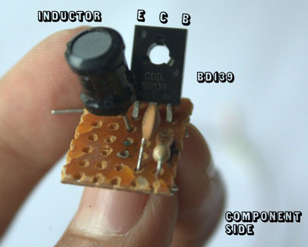
This version uses a powerful high-frequency switching transistor (BD139), and powerful transistors can enhance the effect. The so-called "the stronger the responsibility, the greater the responsibility."
Therefore, the use of this device requires great care and cannot be used near any sensitive electronic device (especially hard drives) because it is capable of generating high frequency environments, which can easily damage your gadget! Take appropriate safety measures with the work of the transformer and use insulated bushings as there is a danger of electric shock. (instead of using a power adapter or battery).
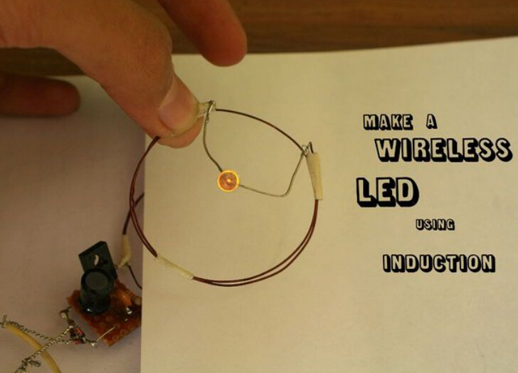
This wireless LED light is simple to make and can be used to demonstrate and study the principles of electromagnetic induction. Making materials is also very easy to get.
material:
1. 2 x 2 inch coil
2. 33k resistor
3. A 100nF capacitor (code: 104)
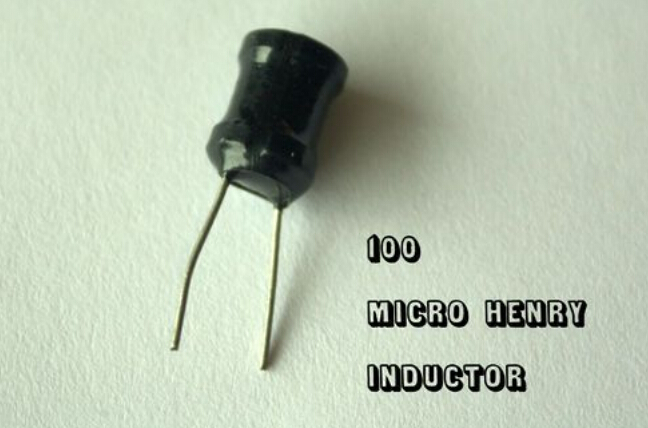
4.100μH (microhenry) inductor
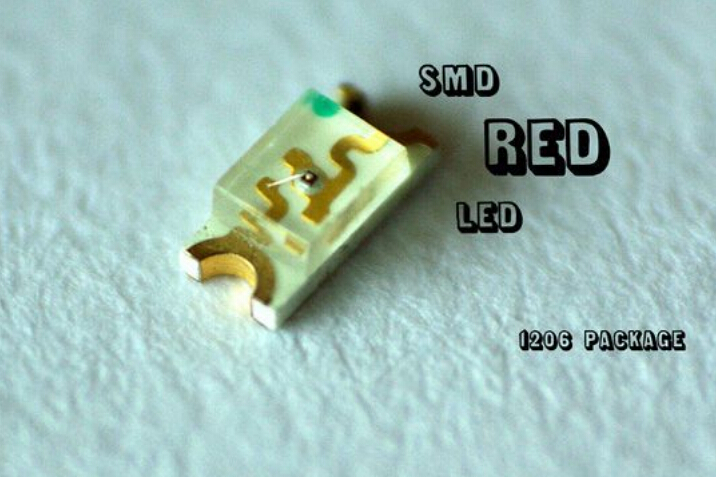
5. One LED (red/orange/red patch works best)
6.BD139 transistor (or the same function)
7. Bridge rectifier (purchase my 1N4148 diode)
8. A perforated plate (3x3cm)
9. Wire, Tin, Power (6-12V)
The first step: collecting materials
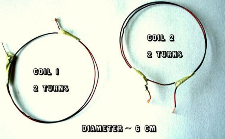
1. The coil can use the old magnetic ring
2. Transistors (BD139), resistors (33K - orange / / orange / / orange) and capacitors (100nF - 104) are quite common and can be purchased from a local electronics store.
3. The inductor can be disassembled from the old circuit board or it can be made by winding a coil around the ferrite core.
4. Make a small bridge rectifier.
Step 2: Mini Bridge Rectifier
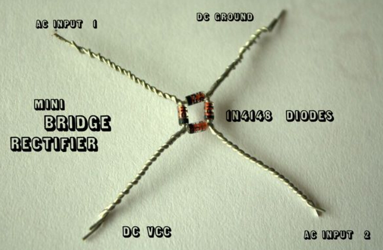
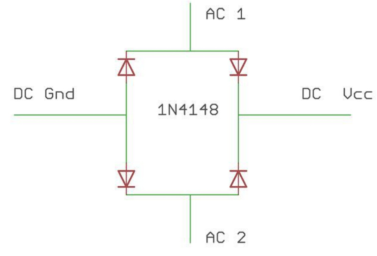
You need 4 1N4148 diodes.
1. Connect 4 diodes one by one according to the schematic.
2. Twist the wire (note the polarity of the diode, the black line indicates the negative).
3. Solder together.
4. In this way, the rectifier bridge is ready.
I used a rectifier bridge because I used AC power (6-12V), but you can skip this step, just use the battery.
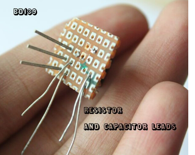
The third step: welding circuit
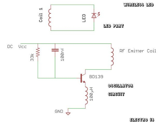
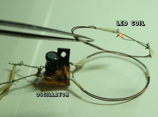
Oscillation circuit:
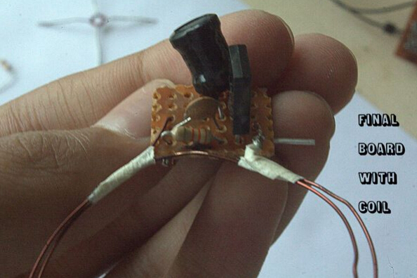
1. Follow the schematic soldering circuit as shown. (on the perforated plate)
2. You can also make it on the breadboard.
3. Be careful when soldering the coil and try not to deform it. Its shape must be perfectly round and in a plane.
LED part:
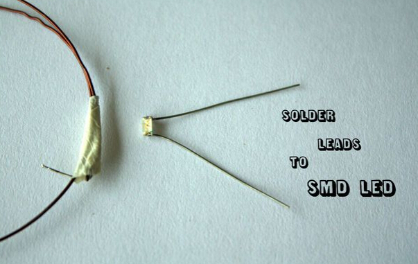
1. If you are using a SMD LED, solder a pair of leads on the pad.
2. If you are using a plug-in LED, solder the lead angle directly to the coil (no need to care about polarity).
The fourth step: processing
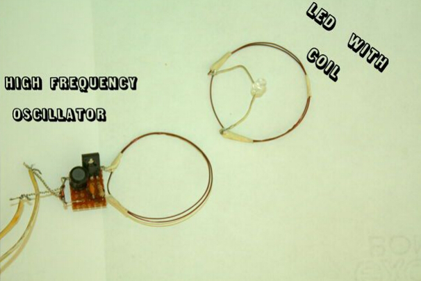
This production is mainly applicable to the principle of mutual induction. The magnetic flux is generated by the transmitter coil and is connected to the secondary coil (coil and LED), so that an electromagnetic field is generated in the coil.
Step 5: Test and troubleshoot
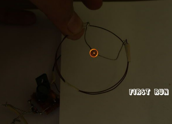
Circuit test:
1. Connect the oscillator to the DC power supply (6-12V depending on your transistor)
2. Place the drive coil on a stable surface.
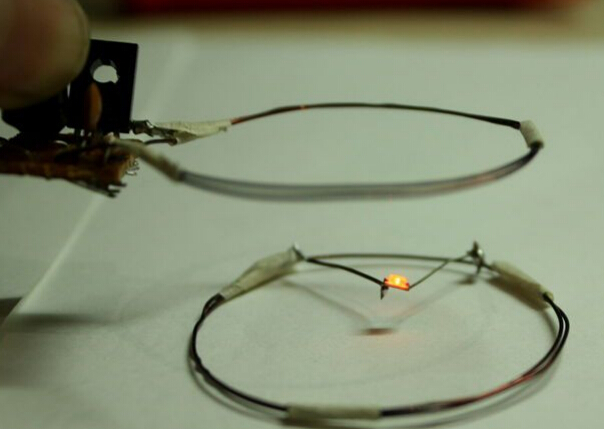
3. Hold the LED coil so that the two coils are in parallel plane.
4. Bring the LED coil close to the oscillating coil (do not touch)
5. The temperature of the transistor may rise a little, but it doesn't matter!
6. Success.
Troubleshooting:
1. Check the welded joints.
2. Avoid any bad contact with the oscillator board.
3. Make sure the coil is circular and does not deform.
4. Keep the coil at the optimum distance.
5. If the coil is a little tilted, the LED will not be so bright.
Epoxy resin seal type NTC Temperature Sensor with the properties of good stability, fast response, temperature resistance, convenient to use, has been already applied to air conditioner, automotive, electrical appliance and induction cooker. Temperature range is from -30°C to 105°C.
Epoxy Resin Seal Sensor
Epoxy Resin Seal Sensor,Stability Sensor,Greenhouse Sensors,Bus Sensor
Feyvan Electronics Technology Co., Ltd. , http://www.fv-cable-assembly.com