Michael Jones, Linear Technology
Recently, some people have asked about the use of built-in fault management and PMBus (Power Management Bus) communication technology. This problem can be divided into two levels: the impact of using PMBus on fault-off decision-making, and how can we construct fault records covering the entire system? Before digging into the applications of these two PMBus, let's look at the PMBus specifications and the intentions of PMBus developers.
The PMBus specification covers alerts, faults, and responses from individual devices; there are two methods for delivering fault information, namely Alert Response Address (ARA) and Host Notify Protocol (HNP). The ARA will initially interrupt the board controller by issuing ALERTB, and the controller will use the PMBus address query to collect a list of all devices using ALERTB.
The HNP is started by the device, after which it becomes a master PMBus and the STATUS_WORD is transmitted directly to the board controller. In practice, the device will respond first and then notify the board controller. This process protects the device and the load side and ensures the fastest response to a fault event by stopping the power transfer.
PMBus content
There are still two aspects of PMBus that have not been resolved: 1. Interaction between devices; 2. Failure records.
Both of these issues were intentionally shelved because the PMBus committee believes that leaving these functions to the manufacturer's own R&D solution is more appropriate. Of course, there are many ways to develop these functions: Use PMBus and board controllers, or use built-in functions. These are basically the basis for the content of the questions asked. The following begins with commentary.
A prototype system was constructed using the reference design of the board controller. This system uses a multi-threaded RTOS real-time operating system (multi-threaded RTOS). This prototype is not the best example of computation, but it does produce practical data that may not even achieve such results in practice.
On the hardware side, Freescale's Kinetis K60 is used with virtual static access memory (PSRAM) and ferromagnetic core memory (FRAM). Use PSRAM for convenience: My system already has a hard drive. The use of FRAM is due to the fact that the data is only sent out at the last frequency of the write transaction, there is no need to write a block, and the number of writes can be very large before the aging expires. On the PMBus device, I use the LTC3880, LTC2974, and LTC2977. I built a power load on VLT 0 of the LTC3880 to generate a fault event.
Telemetry operates in its own thread, failure handling is in another thread, and there are application threads that have lower priority privileges. The application works roughly as follows:
1.ALERT/send when overcurrent occurs;
2. Obtain the address through ARA;
3. Read STATUS_WORD;
4. Make a Power off decision and execute it;
5.STATUS_WORD is stored in FRAM;
6. The output current is read from all 13 power terminals;
7. The output current is stored in FRAM;
8. Set the retry timer;
9. Perform Retry.
This is only an approximate simulation because if more than one power supply fault occurs at the same time, more states are stored in FRAM. This situation is very common because overcurrents can cause low voltages, and interactions between multiple power supplies can occur.

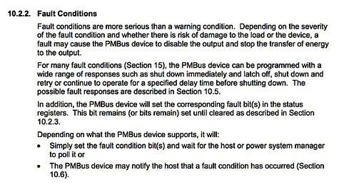
Telemetry on the I2C bus takes about 40ms for all 13 power supplies
The waveform above captures the results. We can see that telemetry is performed on the I2C bus. All 13 power supplies take about 40ms. The result is stored on the SD memory card and takes less than 200ms. However, the next telemetry will take 300ms. This shows that SD memory cards are suitable for use in telemetry, but are not suitable for use in fault records. The reason for this is quite complex, but just remember that the SD memory card contains the FAT file system, so the number of jobs includes steps such as reading the directory structure.
Multiple steps can be seen on the ALERT/pin, and the total time for troubleshooting is approximately 50ms. This time includes performing multiple ARAs, reading status from multiple power supplies, collecting some output current readings, and then storing the data in FRAM. A failure event triggers the closing process and takes more than 400ms. The last step is to perform a retry procedure.
There are good news and bad news here. The good news is that in a system with 13 power supplies, it is necessary to record multiple fault events to the log. The procedure for storing fault data can take 50 ms. This data is very close to the worst case value. General failure events can be completed in less than 10 ms from collection to storage of data. If you carefully observe the fault event from the start of the retry, you can see multiple FRAM transfers because the execution of ARA is very fast. In this situation, the system needs only a few milliseconds to capture the original fault event.
The bad news now: It takes hundreds of milliseconds to shut down the power supply. Yes, I know this is not an ordinary real system. The purpose is just to let everyone know how long it takes for the system to turn off the power without taking into account how your PMBus fault response is set.
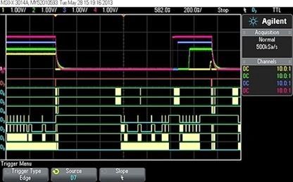
Failure to consider power shutdown time required for PMBus fault response
Now switch to immediate shutdown mode and notice how quickly the power supply turns off. Let's zoom in to see:
Power off time to switch to immediate shutdown mode
After switching to immediate shutdown, the system must spend 2.5ms to turn off the power supply. This time includes reading the status register, sharing the bus with telemetry, and commanding the power off. Therefore, this value may change slightly, sometimes faster, and sometimes slower. The best possible condition is to read the status after an ARA, followed by a global close instruction. The use of a read byte (length 3 bytes), read status characters (5 bytes), global off (6 bytes).
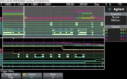
At a frequency of 400 kHz, the time is 375 us. However, this does not include the consumption time of any drivers. Note that the three power supplies will slowly slow down because their load is only a few milliamperes. Although the power supply is turned off quickly, it still requires a load to depress to ground potential. This is another problem. Although this is much better, can we still do better? Of course, if the device has a built-in fault management mechanism, there is room for improvement. Let's see what we can do.
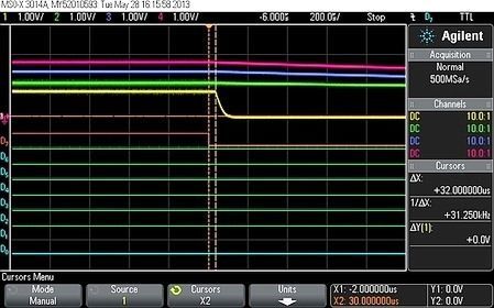
Power off time of built-in fault management mechanism
The power supply closes within 30us and drops to ground potential in less than 100us. This is a lightly loaded power supply. If I use a 20 amp load, then the speed of closure is much faster. Such a short delay does not have to be compared with other alternatives - it is a simple comparison. Your program code does not have to do this because it has no effect on the built-in failure response.
What is the final conclusion? Using PMBus for telemetry, system-wide fault logs are really useful. You can collect data for the entire system and then quickly store it in non-volatile memory. In addition to the built-in fault logging feature on most devices, more value can be added.
In general, the built-in log records more detailed and useful information about the source of the incident. External logs usually have timestamp information for the entire system. At the same time using two kinds of logs, the chance of a successful diagnosis will greatly increase. However, it is not a good idea to use a serial port to protect the load. For a 400kHz serial bus, the theoretical best practice is 10 times slower than the built-in solution.
We look at the issue from different perspectives. Assuming a serial bus must turn off the power supply within 30us, how fast does it have to be? In the ideal condition of 14 bytes, it is equal to 112 bits. Allow a little time for interrupt latency and/or decision logic to calculate about 4MHz. Then consider what happens if there are 10 devices on the bus at the same time. Will need 40MHz. Then consider a 100-power system...
In both cases, load protection and fault logging, the functionality of the PMBus is sufficient to respond. However, in terms of logs, the best practice is to build improvements in the logs. In terms of load protection, it is best to use device functions to share fault information. This is precisely what the PMBus Committee wants to achieve. It is to establish a shared standard to solve problems and also support innovation and R&D.
DMX LED Panel HS is Led panel with Housing. The cover of lceiling led panel can be cusomized. It used high-brightness Led chips, SMD5050 Led, clear and pleasant light beam, bright and non-glare. We will design the housing of led panel according to your installation area. It can used in outdoor and indoor.
Photo show of Dmx Led Panel Hs:


Dmx Led Panel Hs,Led Rgb Panel,High Brightness Dmx Led Panel,Dimmable Led Panel Light
Shenzhen Iseeled Technology Co., Ltd. , https://www.iseeledlight.com