introduction
This article refers to the address: http://
With the popularity of automobiles and the acceleration of driving speed, the number of traffic accidents and casualties is also increasing year by year. In the event of a car crash, how to effectively protect the safety of drivers and occupants is an urgent problem to be solved. Airbags have become popular as passive protection devices for use with seat belts and have become one of the main equipment for protecting occupants in automotive components.
The airbag control system can be divided into three types: mechanical, analog electronic and embedded. For mechanical and analog electronic control systems, due to hardware limitations, flexibility is greatly limited and applications are decreasing. The new generation of airbag control systems are embedded control systems with microcontrollers. The control algorithm of the embedded control system is realized by software, which greatly improves the flexibility of the system, and has the functions of recording accident data and communicating with the host computer.
The airbag requirements of the car can detect the occurrence of a car collision accident and control the airbag detonation in a very short period of time. In order to achieve the above objectives, the microcontroller of the airbag control system is required to have a strong computing capability and an adequate I/O port. Based on this, the high-performance 32-bit microcontroller is selected to research and develop a more practical automotive airbag control system, which has certain application and reference value. Based on the research of advanced control systems at home and abroad, this paper proposes a design scheme of automotive airbag control system based on ARMCortexM3 core 32-bit microcontroller, and carries out trolley and real vehicle tests respectively.
1 ARMCortexM3 core and microcontroller LM3S1138
ARM has developed a 32-bit CortexM3 core processor for low-cost applications. The processor effectively utilizes chip space, highly integrated peripherals, and a system-on-a-chip (SoC) with the core. The ARM Cortex M3 processor combines the Thumb2 instruction 32-bit Harvard microarchitecture. Thumb2 technology increases code density, reducing memory usage by 26% over 32-bit encoding and 25% performance over 16-bit encoding. By reducing the clock frequency, providing lower power consumption, lowering R&D costs and increasing business efficiency. The Tail-Chaining interrupt technology is implemented on the chip, which reduces the delay between interrupts to 6 machine cycles and reduces the interrupt by 70% in practical applications.
The microprocessor of this system selects TI's LM3S1138 industrial grade microcontroller based on ARMCortexM3 core. It has an operating temperature range of -40 to 85 ° C and has good electromagnetic compatibility and can be used in automotive electronics.
2 system working principle and design
2.1 How the system works
The airbag control system is mainly composed of a sensor, a self-test circuit, a trigger circuit, a communication circuit and an alarm circuit, as shown in FIG.
The working principle is as follows: After power-on, the system performs a self-test to determine whether the trigger circuit can work normally. If there is a fault in the trigger circuit, the alarm circuit will sound and light alarm, indicating that the system is not working properly, and the driver is notified to repair in time. When the self-test is normal, the signal measured by the acceleration sensor MMA7260 is continuously sampled by the 32-bit microprocessor LM3S1138. When the car is subjected to a high-speed collision within a certain angle, the system immediately triggers the igniter in the airbag package after being confirmed by the algorithm analysis. The airbag is quickly filled with gas, blocking the possible collision between the driver and the automobile component, and passing the airbag upper row. The throttling damping of the air vents buffers the kinetic energy of the driver to protect the driver.
2.2 System hardware design
2.2.1 Acceleration measurement circuit
This article selects Freescale's silicon capacitive acceleration sensor MMA7260. It features signal amplification, low pass filtering and compensation. The device's zero-acceleration bias, full-scale range, and filtering characteristics are set by the manufacturer and do not require external passive components. Due to the high integration and reliability of the sensor manufacturing process, external interference is minimized. MMA7260 is directly integrated into the IC package, which can be directly soldered to the PCB board for easy debugging.
The LM3S1138 processor has an 8-channel 10-bit ADC with a sampling rate of 1M/s and is accurate enough for airbags. After the sensor measures the acceleration, the voltage value is output from the corresponding output pin. The voltage value is analog-to-digital converted by the ADC built into the LM3S1138 processor and stored in an array of software settings.
The hardware schematic diagram of the acceleration measurement circuit is shown in Figure 2.
This system only uses the X and Z axes of the MMA7260 three-axis acceleration sensor for horizontal collision judgment. The X-axis direction measures the acceleration of the frontal collision of the car, and the Z-axis direction measures the acceleration of the vertical direction of the car. When the car drives at high speed through the ditch and awning, it will cause the sensor to generate a large signal even if there is no collision. This signal is superimposed on the collision waveform of the low-speed collision, causing the microcontroller to mistakenly think of a high-speed collision, and then a false explosion occurs. In view of this, when the car Z axis (vertical direction). When a large acceleration is generated, the airbag is designed not to detonate regardless of the acceleration in the X-axis direction. It avoids the unnecessary loss caused by the airbag detonation when the car drives through the ground road barrier at high speed, and enhances the anti-interference of the road surface.
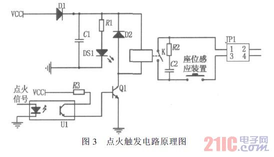
2.2.2 ignition trigger circuit
A 20 mA current pulse is required due to the burst of the air bag gas generator. If the I/O port of the LM3S1138 is used to directly output a high level for detonation, the drive is too small to meet the requirements. The system uses an electromagnetic relay that can drive high-power loads under the control of the LM3S1138 output port. Since the relay will generate more obvious interference, the anti-interference circuit is added around the relay and used together with the optocoupler to electrically isolate the processor from the trigger circuit. When a collision occurs, the airbag is not protective to adults or children who are too short, and the huge impact of the detonation will even kill him. In order to achieve safe ignition and intelligent ignition, the system sets a seat pressure sensing device on the trigger circuit. If an adult is seated, the device is closed and the ignition circuit is working properly. Conversely, if the device is disconnected, it means that no one is seated or only a small adult or child is seated, and the trigger circuit cannot form a loop. At this time, even if the car collides and the algorithm issues an ignition signal, the airbag does not blast. In this way, it not only prevents the economic loss caused by detonating the airbag in the unoccupied state, but also avoids the damage caused by the airbag to the short adults and children. The schematic diagram of the ignition trigger circuit is shown in Figure 3.
2.3 System software design
The system simplifies the software development environment with the CortexM3 core processor.
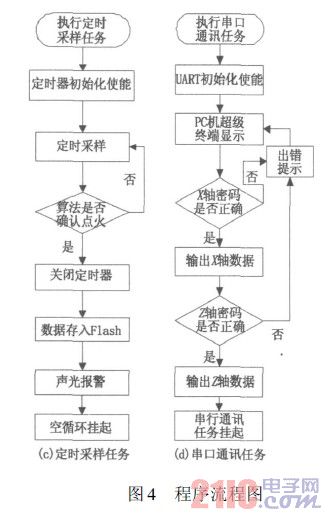
For a series of microcontrollers such as the LM3S1138, TI officially provides C-based (according to the ANSIC standard) for free. The driver library, which contains a large number of firmware function libraries, has a corresponding routine for each peripheral, which can be easily modified and ported according to the needs of the application. Therefore, in software programming, software management of the assembler program is not required, and the driver library C language function can be used for programming development. When developing an application, the modular design of the driver library routines is not only easy to program, but also simple and readable. For large programs, using a driver library enhances reliability and security while reducing maintenance costs. Therefore, the system software program uses the driver library routine provided by TI to carry out modular programming, and divides the whole system program into several small programs or modules for independent design, programming and testing. Finally, each module is built into a complete project to complete the application design. The whole project is divided into four modules: main program, startup task, timing sampling task and serial communication task. The flow chart is shown in Figure 4.

2.3.1 main program module
In order to increase the execution efficiency of the system and realize the multi-tasking program operation, the system is embedded and the μC/OS-II operating system is embedded. The task module is started in the program flow chart as a common mode of the program when the μC/OS-II operating system is embedded.
2.3.2 Starting the task module
When the program is running, the startup task is executed first, and then the communication task or the timing sampling task is executed according to the button condition.
2.3.3 Timing sampling module
In the software, the acceleration is sampled every 1 s and A/D conversion is performed and stored in Flash. If a collision accident occurs and the ignition condition of the algorithm is met, the current data storage address is recorded, an ignition command is issued in time to activate the airbag, and at the same time, 90 data points are resampled. When analyzing the scene, 90 data before the collision and 90 data after the collision can be recorded in the built-in Flash of the LM3S1138, which is the cause of the black box information analysis accident.
This system uses a moving window integration algorithm that adds vertical quantity. Due to space limitations, it will be discussed in subsequent articles.
2.3.4 Serial Communication Module
After the accident, the PC reads the data in the black box of the airbag control system through the serial port as an analysis of the accident. Developers can set their own passwords for reading the horizontal and vertical acceleration data of the black box.
3 performance test
At present, the 5-inch (1 inch = 254 cm) 30 ms criterion is commonly used in the automotive industry to determine the optimal ignition timing of the airbag. During the collision of the car, the first 30 ms of the occupant moving forward 5 inches relative to the vehicle body is the optimal ignition timing of the airbag. This is based on the fact that the distance between most of the seat belts of the seat belt and the steering wheel is 12 inches, the thickness of the airbag after inflation is about 7 inches, and the time from the burst to the gas filling is 30 ms. When the air bag is full of gas, the occupant is just in contact with the air bag, and the air bag protection is optimal. If the airbag is ignited too early, when the occupant touches the airbag, the airbag is deflated and does not provide protection.
When the airbag is ignited too late, the occupant will injure the occupant and even die due to the inertia moving forward. So the best ignition time is the key to designing the airbag controller. The system uses the integration window algorithm and ARMCortex processor to achieve better results, and the test results are basically consistent with the standard.
3.1 trolley test
The trolley test was carried out at the Automobile Collision Laboratory of the Science and Technology College of Nanchang University, as shown in Figure 5. After the collision, the time when the occupant moves forward is lagging behind the collision time. The size of the lag depends mainly on the energy absorption performance of a certain model. Since there is only an airbag control system on the trolley, there is no energy absorbing device, and the energy absorption is almost zero. Therefore, in this test, the collision time is considered to be the time when the occupant starts to move forward. The trolley is towed by the rope on the taxi track. The speed is gradually increased from 40km/h to 60km/h. The test process was recorded by a high-speed camera, and the airbag was turned on after the collision time by slow-motion recording. The data is shown in Table 1.
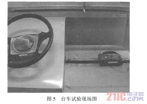
The test data shows that the deviation between the airbag opening time and the optimal ignition timing is small, and there is no phenomenon that the airbag is injured by the occupant or premature air leakage.
3.2 Real vehicle test
In a motor vehicle testing center in the country, a real car test was carried out with a certain type of domestic car. The type of collision is a frontal collision. A dummy is placed on the driver's seat and the seat belt is fastened. The collision speed is 60km/h. The collision object is honeycomb aluminum. The dummy sensor data acquisition system has a sampling frequency of 1 kHz. According to the preliminary test, the energy-absorbing deformation process of this model lasted for about 50ms, so the procedure of the airbag control system was modified before the actual vehicle test. The test site video screenshot is shown in Figure 6.
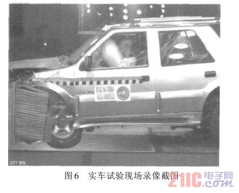
Through the playback of the high-speed camera recording placed on site, it can be seen that the airbag is accurately blasted after the occupant moves forward for 30 ms. The actual vehicle test shows that the safety system control system can accurately control the optimal ignition timing of the airbag.
4 Conclusion
Since the airbag requires the handling of collision accidents in a very short time, the control system is required to complete the real-time processing and complex calculation process in an instant, that is, it requires a higher calculation speed and a smaller time lag to adapt to the automobile. Real-time control requirements for airbags. The general 8-bit MCU is simple to program and easy to apply, but the signal processing capability is not strong. The system uses a 32-bit high-performance microcontroller LM3S1138 based on ARMCortexM3 core, embedded in μC/OS-II operating system, and completes the system design by using the moving integral window blasting algorithm. The trolley test and the actual vehicle test show that the system can accurately control the optimal ignition timing of the airbag, thereby effectively protecting the safety of the driver. The system software design part uses TI's official freely provided driver library, and the modular design simplifies the development process. The LM3S1138 microcontroller is a system on chip (SoC). The peripheral resources such as ADC, analog comparator, and flash memory are integrated and the price is low, so the system built is high in integration, small in size, and low in cost. The LM3S1138 has up to 46 I/O ports, which increases the scalability of the system. Based on this, the multi-level intelligent car airbag control system can be developed.
The shipboard medium voltage power cables are intended for shipboard and off-shore building to transmit power.
Standards applied: IEC60092-350, IEC60092-354, IEC60092-360, IEC60228, IEC60332-1-2, IEC60332-3-22, IEC61034, IEC60754 and IEC60684-2.
Product making: factory name, type, rated voltage core.
Making: colour tape.
Medium Voltage Marine Power Cable
Different Types Of Electrical Cable,Medium Voltage Marine Power Cable,Electrical Marine Power Cables,Marine Control Power Cable
Jiangsu Jiangyang Special Cable Co,.Ltd. , https://www.jymarinecable.com