Traditional low efficiency circuits:
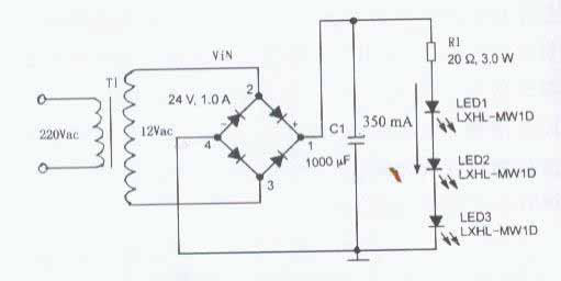
figure 1
Figure 1 is a traditional low-efficiency circuit. The grid power supply is stepped down by a step-down Transformer. After bridge rectification and filtering, the three LEDs are stabilized by resistor current limiting. The fatal disadvantage of this circuit is that the existence of resistor R is necessary. The active loss on R directly affects the efficiency of the system. When the R partial pressure is small, the voltage drop of R accounts for 40% of the total output voltage, and the active loss of the output circuit on R has accounted for 40%, plus the transformer. Loss, system efficiency is less than 50%. When the supply voltage fluctuates within ±10%, the current flowing through the LED will change by ≥25% and the power variation on the LED will reach 30%. When the R partial pressure is large, when the power supply voltage fluctuates within ±10%, the power variation to the LED can be reduced, but the system efficiency will be lower.

figure 2
Figure 2 is based on Figure 1 with an integrated voltage regulator MC7809, so that the output voltage is basically stable at 9V, the current-limiting resistor R can be used very little and will not overload the LED due to the instability of the power supply voltage. However, in addition to ensuring a substantially constant output of the LED, this circuit is still very inefficient. Because the voltage drop across the MC7809 and R1 is still a large percentage, its efficiency is only about 40%.