Overview
Temperature measurement is required in many places. When designing a temperature telemetry system, a battery-powered, very low power module is typically required. Traditional temperature measurement methods are more, but whether using discrete transistors, thermistors, or thermocouples, power consumption can not be reduced. This article describes a viable solution to meet low power requirements. It uses a very low power MCU with Flash memory, as well as a digital temperature sensor, liquid crystal module (LCD) and a 32kHz watch oscillator. The outstanding feature of this program is energy-saving and durable. It can work continuously for more than 10 years with only one button battery.
working principle
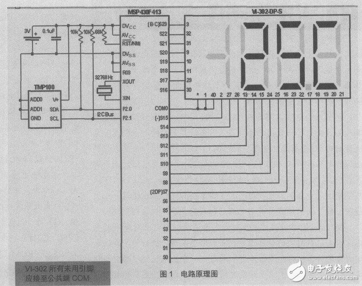
The power supply of the MCU expansion system shown in Figure 1 is a CR-2032 button-type lithium battery with a capacity of 220 mAh. To allow the system to meet the requirements of continuous operation for 10 years (87,700 hours), the maximum allowable load current can be calculated in the following way:
220mAh / 87,600 hours = 2.51 A
This temperature measurement system not only measures the temperature, but also continuously displays the measurement results. When the system is in single-step mode, the TMP100 temperature sensor automatically enters the shutdown mode every time it completes a measurement. The typical power consumption is 0.1 A at this time; when the system is in the energy-saving low-power mode (LPM3), the crystal oscillator, LCD driver and The 16-bit timer continues to operate, with a typical power consumption of 0.9 A for the MSP430 and 1 A for a 3-bit half LCD.
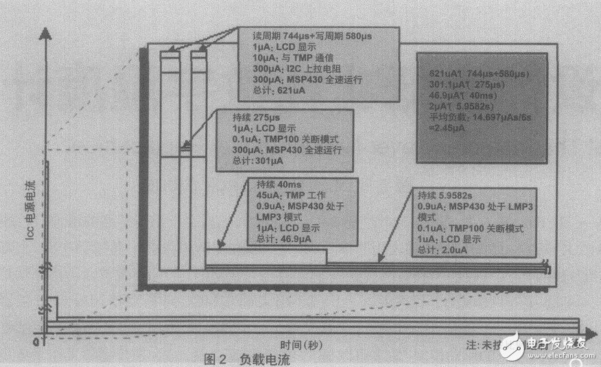
The power consumption of each duty cycle of the system is shown in Figure 2. The average power consumption of the temperature sensor, MCU and LCD is 2.45 A. In order to maximize battery life, the system is in standby mode for most of the work cycle.
Hardware design description
The battery plus a 0.1 F decoupling capacitor forms the power supply for this system. The reset terminal of the MCU is connected to a 68k pull-up resistor, and the clock pulse (ACLK) is taken from the crystal for the clock of 32.768KHz. Connect a 10K pull-up resistor to the SCL (clock) and SDA (data) of the I2C bus.
working principle
The MCU is connected to the temperature sensor via an I2C bus. The I2C bus occupies two MCU input and output lines, and the communication between the two is completely dependent on software. The address of the temperature sensor can be set via 2 address pins, which allows 8 such sensors to be connected simultaneously on an I2C bus. In this scenario, the 7-bit address of the sensor has been set to 1001000. When the MCU needs to access the sensor, it must first issue an 8-bit register pointer and then issue the address of the sensor (7-bit address, low-order is the WR signal). There are three registers in the sensor for the MCU to use. The 8-bit register pointer is used to determine which register the MCU will use. In this scenario, the main program constantly updates the sensor's configuration registers, which causes the sensor to operate in single-step mode, and the temperature is measured every time it is updated.
To read the contents of the sensor measurement register, the MCU must first send the sensor address and register pointer. The MCU sends a start signal, then sends the sensor address, then sets the RD/WR pin high to read the measured value register.
In order to read the 16-bit data in the sensor measurement register, the MCU must perform two 8-bit data communication with the sensor. When the sensor is powered up, the default measurement accuracy is 9 bits and the resolution is 0.5 C/LSB (range -128.5 C to 128.5 C). This solution uses the default measurement accuracy. The sensor can be reset as needed to increase the measurement accuracy to 12 bits. If only a general temperature indication, such as a thermostat, is required, then a resolution of 1 C will suffice. In this case, the lower 8 bits of the sensor data can be ignored, and only the high 8 bits of data can be used to achieve the resolution 1 C design requirement. Since the register is read in the order of the first 8 bits and the lower 8 bits, the lower 8 bits of data can be read or not. There are two advantages to reading only the upper 8 bits of data. The first is to shorten the working time of the MCU and the sensor, and reduce the power consumption. The second is that it does not affect the resolution index.
After the MCU reads the measured value of the sensor, it will then convert and display the result on the LCD. The whole process includes: judging the sign of the display result, converting the binary code to the BCD code, and transmitting the data to the relevant register of the LCD.
After the data is processed and the results are displayed, the MCU issues a single-step command to the sensor. A single-step command causes the sensor to initiate a temperature test and then automatically enters standby mode until the analog-to-digital conversion is complete. After the MCU issues a single-step instruction, it enters LPM3 mode. At this time, the MCU system clock continues to work, and a timer interrupt is generated to wake up the CPU. The length of the timing can be adjusted programmatically to suit the needs of the specific application.
Functional expansion
The program code for implementing the above scheme is only about 400 bytes, and the MCU's Flash program memory is as much as 8k. In addition, although the MCU has 256 bytes of RAM, one byte of the program is not necessary. This 256-byte RAM and those unused in-system programmable (ISP) flash memory can be used to record historical data. In addition, the MCU has 22 input and output lines, a double-ended voltage comparator and a complete three-channel 16-bit timer TImer A. These free resources can be used to implement other commonly used functions such as keyboard and composite ringtones. , analog to digital conversion, battery power detection and serial communication functions. Since the system clock uses a 32 kHz watch crystal, the clock function (RTC) can be implemented using a timer interrupt.
Since the I2C bus is used between the temperature sensor and the MCU, it is possible to connect more sensors by assigning different addresses. For example, a TMP100 sensor with a 3-bit address can connect up to 8 sensors at the same time on the bus.
summary
This paper introduces the software and hardware design of a very low-power temperature measuring device. The solution adopts MCU, sensor and LCD display. It has the advantages of perfect function, energy saving and durability, simple structure, small size and low price. The temperature measuring device manufactured according to this scheme can not only meet the measurement requirements, but also can work continuously for more than 10 years without using a 3V battery to supply the battery without having to replace the battery.
Inspection Lifting Column,Motorized Lifting Column,Single Column Car Lift,Telescopic Pneumatic Cylinder
Kunshan Zeitech Mechanical & Electrical Technology Co., Ltd , https://www.zeithe.com