Abstract: In order to improve the development efficiency and development quality of AMT system, an AMT in-loop simulation experiment system was developed. The real vehicle AMT related components were replaced by simulation models, and the dynamic model of vehicle transmission system and its components was established. The corresponding program design is carried out to simulate the engine speed and vehicle speed of the real vehicle. The AMT electronic control unit is verified before the actual vehicle test, which provides a convenient and reliable experimental platform for the development of the AMT electronic control system.
Key words: AMT; in-loop simulation; vehicle dynamics; simulation model
0 Introduction Heavy-duty vehicles have the characteristics of large total mass, complicated working conditions and many gears. It is of great practical significance to reduce the driver's handling difficulty and labor intensity and realize automatic shifting of heavy vehicles. The electronically controlled mechanical automatic transmission (AMT) has the advantages of high efficiency, low cost, easy manufacture, and easy operation, and can meet the power transmission requirements of heavy vehicles, so it has broad application prospects in heavy vehicles. The traditional AMT system development requires a lot of debugging on the real car, which causes waste of time and money. The AMT-in-the-loop simulation experiment system can not only simulate the performance of the vehicle under normal working conditions, but also can modify the simulation conditions to obtain the vehicle response and evaluation corresponding to the vehicle under extreme conditions and emergency conditions. The advantages and disadvantages of the control strategy provide convenience for the development of the AMT electronic control unit, which can significantly improve the development efficiency and development quality of the AMT system.
The AMT in-loop simulation experiment system mainly includes AMT electronic control unit, vehicle dynamics simulation module, mechanical simulation execution mechanism, and information input module. This paper mainly designs the vehicle dynamics simulation module, and establishes the vehicle dynamics model, including the engine model, the clutch model and the longitudinal dynamics model of the vehicle transmission system, and uses C language for programming, using the external input information, the straight line to the vehicle. Simulation of driving conditions, simulation of engine speed, transmission intermediate shaft speed, vehicle speed and other parameters to verify the feasibility and reliability of AMT electronic control unit performance.
1 AMT in-loop simulation experimental system structure and working principle AMT in-loop simulation experimental system shown in Figure 1, the system is mainly composed of AMT electronic control unit. TCU vehicle dynamics simulation module, information input module, clutch actuator, gearbox selection shift actuator, sensor system, instrument panel and liquid crystal display module and information real-time detection module. The vehicle dynamics simulation module is used to simulate the vehicle kinematics; the information input module has information such as an electronic accelerator pedal, a brake pedal, a vehicle load knob, a road gradient knob, a parking brake switch, etc.; the clutch actuator adopts a real vehicle. The clutch actuator uses a spring to simulate the clutch pressing force; the gearbox selection shifting actuator adopts the actual vehicle selection shifting actuator; the sensor adopts the real vehicle's selected shift position sensor and the clutch displacement sensor; the instrument panel adopts the real vehicle instrument It is used to display information such as vehicle speed and engine speed; the liquid crystal display module is used to display information such as accelerator pedal opening degree, brake pedal opening degree, vehicle load, road gradient, clutch stroke, and shift position. 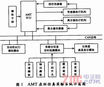
When the experimental system ignition switch is turned on, the vehicle load and road gradient information are set, and the driver's driving intention is simulated by the accelerator pedal and the brake pedal. The collected information such as the accelerator pedal opening degree, the brake pedal opening degree, the vehicle load, the road gradient, the clutch displacement, and the gear information sent by the AMT electronic control unit TCU are sent to the established vehicle dynamics model through the CAN bus. Vehicle kinematics simulation. The simulated engine speed, transmission intermediate shaft speed, and vehicle speed are sent to the TCU. The TCU controls the clutch engagement and the gearbox selection shift according to the built-in control law (change selection law, clutch engagement law, etc.) to test the AMT system. Performance feasibility and reliability.
2 Vehicle dynamics system simulation model
2.1 Vehicle model The vehicle is powered by the engine, transmitted to the drive wheels through the drive train, and converted into driving force to overcome the road resistance and drive the vehicle. The driving equation of the vehicle is: 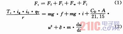
Where: Ft is the driving force; Ff is the ground rolling resistance; Fi is the road surface resistance; Fw is the air resistance; Fj is the acceleration resistance; Tc is the friction torque transmitted by the clutch; ig and io are the transmission ratio and the main reduction ratio respectively ηT is the mechanical efficiency of the drive train; r is the wheel radius; m is the total mass of the vehicle; g is the gravitational acceleration; f is the rolling resistance coefficient of the ground and the tire; i is the road gradient; CD is the air resistance coefficient; A is the windward area ; u is the speed of the car; δ is the conversion factor of the car's rotating mass. 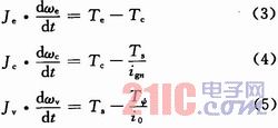
Figure 2 shows the three-mass system dynamics model of the vehicle transmission. The dynamic equations of each part are: 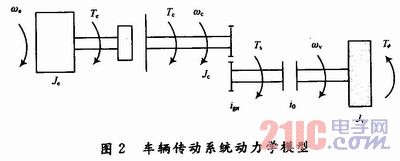
Where: Tc is the output torque of the engine; Tc is the friction torque transmitted by the clutch; Ts is the synchronous torque that varies with the transmission gear; Tψ is the resistance torque of the wheel, including the air resistance torque, road resistance torque and system Dynamic torque, etc.; ωe is the engine crank angular velocity (also the clutch active blade angular velocity); ωc is the transmission input shaft angular velocity (also the clutch follower angular velocity); ωv is the transmission output shaft angular velocity; and Je is the engine and clutch active portion equivalent rotational inertia; Jc is the clutch driven part, the transmission part equivalent moment of inertia; Jv is the equivalent moment of inertia of each assembly part fixedly related to the transmission output shaft; ign and io are the transmission nth gear ratio and the main reduction ratio .
2.2 Engine model The engine output torque Te can be obtained from the engine speed characteristic curve. The actual vehicle engine speed characteristic curve (ie, the torque characteristics of the engine at different accelerator opening and speed) is used as an engine model, and the engine output torque Te is determined by the engine speed and the accelerator pedal opening degree. In the AMT-in-the-loop simulation experiment system, the engine output torque and the crankshaft opening degree can be obtained according to the known engine speed characteristic curve by the engine speed and the actual opening degree of the accelerator pedal obtained from the vehicle model. Fuel consumption.
2.3 Clutch Model The clutch transmission torque Tc is related to the operating state of the clutch. The clutch relies on the friction torque between the main driven pieces to transmit power, and controls the working state of the vehicle powertrain by separating and engaging. The clutch working state can be divided into three states: full engagement, complete separation and sliding.
2.3.1 Fully engaged, fully disengaged state These two states are stable and the torque transmitted by the clutch is also determined, ie Tc = Te when fully engaged and Tc = 0 when fully disengaged.
2.3.2 Slip state The slip state is the transition between the first two states, either the transition from engagement to separation or the transition from separation to engagement. From the perspective of the frictional torque transmitted by it, the frictional torque transmitted by the clutch changes from 0 to Te or from Te to 0. This state includes the clutch start engagement process, the engagement process after the shift is completed, and the separation process before the shift start.
(1) Starting engagement process Figure 3 is a schematic diagram of the change of speed and torque during the starting process. Where Tm is the resistance torque that is converted to the wheel on the clutch driven portion; Tcs is the clutch static friction torque, and Δω(Δω=ωe-ωc) is the difference between the clutch disc and the driven disc. 0~t1 stage, Tc 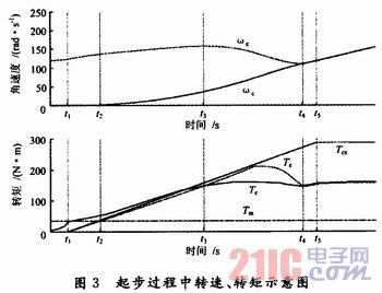
(2) Post-Shift Engagement Process In addition to the start-up engagement process, the transition of the clutch from the disengagement to the engagement also includes a transition from separation to engagement after the end of the shift. Except for the similar situation to the starting process, this process may occur with ωe < ωc (such as the clutch engagement process after the downshift). At this time, the accelerator pedal opening degree is kept constant or increased at a certain speed so that Te>O, and since Δω=ωe -ωc
The expression of the clutch transmission torque when the sliding mode state is obtained by the above three processes is: ![]()
Where: sign(·) is the sign function; z is the number of friction surfaces of the clutch; μs is the static friction coefficient of the clutch friction plate; FN is the normal total pressure on the clutch friction plate, depending on the clutch release bearing position; Rc is the clutch friction plate Equivalent friction radius.
3 Vehicle dynamics simulation program design Based on the established vehicle dynamics model, the main task is to receive the vehicle load, road gradient, accelerator pedal opening and brake pedal opening from the AMT simulation experiment system. Information, gear information from the TCU, and clutch displacement information from the clutch position sensor, simulating parameters such as engine speed, transmission intermediate shaft speed, and vehicle speed. The vehicle dynamics simulation module MCU adopts Freescale's 16-bit single-chip MC9S12DP512, and uses the C language to program the built vehicle dynamics simulation module in the Code Warr-ior IDE development environment. The program mainly includes: system initialization module, data communication module and program main loop module, and the program flow chart is shown in FIG. 4 . 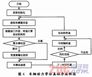
System initialization mainly includes MCU internal clock setting, communication port initialization, watchdog timer setting, etc., to ensure the normal operation of the MCU. The data communication module is configured to receive data sent from the AMT in-loop simulation experiment system. The main program calculates the vehicle acceleration based on the transmission system output torque simulated by the engine model and the clutch model and the resistance torque preset by the AMT in the ring simulation system, and then can obtain the vehicle speed and engine speed at the next moment to achieve vehicle dynamics. Simulation simulation.
4 Conclusion An AMT-in-the-loop simulation experiment system based on vehicle dynamics model was developed. The dynamic simulation model of vehicle engine and transmission system was established, and the driver model and external resistance model were designed as variable parameters. Program design. The application on the AMT ring simulation test bench shows that the parameters such as engine speed and vehicle speed simulated by the model are in line with the actual vehicle driving conditions, and can simulate the extreme working conditions and emergency conditions that are difficult to obtain in the experiment, which is the AMT system. Research and development provide the foundation.
This article refers to the address: http://
PTFE caoted open mesh belting products are used in drying applications where air flow is required.Typical applications include screen print and textile dryers, non-wovens processing and similar processes that require the circulation of hot air.
Our open mesh belting combines a maximum amount of open area with good mechanical strength, which maximize the rate of drying.

Open Mesh Belt,PTFE Mesh Conveyor Belt,Mesh Conveyor Belt,PTFE Coated Open Mesh Fabrics
TAIZHOU YAXING PLASTIC INDUSTRY CO., LTD , http://www.yaxingptfe.com